Programmable time-lapse camera controller
Have you ever wanted to change time? Are you curious about events that happen over days, weeks or months? Do you want to emulate nature documentary video sequences showing thunder clouds developing in minutes or flowers opening in seconds?
Even if you have some electronics knowledge, check the Electro Technology Industry Training Organisation (ETITO) website for advice and a mentoring programme for New Zealand primary and secondary school students. With a few basic hand tools and a digital camera, this programmable camera controller project is for you.
By using components already available at home, costs may be kept to a minimum. A servomotor may be reused from a radio-controlled model and aluminium for the adaptor plate may be acquired from a manufacturer’s scrap bin. Be sure to ask for permission first. All the suggested electronic bits need to have a 6-Volt rating or greater and may be bought from local retailers.
This project combines creating an electronic circuit, building an adaptor plate so that the servo and the digital camera work together, and writing the software code.
Another interesting part of the project is being able to show people your video, produced from the still photographs recorded by this equipment you have created. Choosing the first subject is pretty easy. The author set a camera up in the family room of his own home, when celebrating a birthday. The camera was out of the way and soon forgotten until the video was viewed and resulted in lots of laughs.
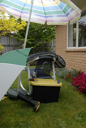
To work effectively outdoors, protecting equipment is a little more difficult. For temporary shelter, umbrellas are great – otherwise a showerproof container with a clear front should be used. Some food containers may be used but the interior must be kept dry or condensation may cause water droplets to form on cold equipment and lenses – not a good environment for electronic gear. To reduce condensation inside an enclosure you can fill the excess space with dry rags or bubble wrap. Be sure the lens and servo can still work properly.
The camera should be set on the lowest resolution and the flash turned off. Make sure the horizon is horizontal and the verticals are vertical – this also makes the video look a bit more professional. Happy time lapsing!
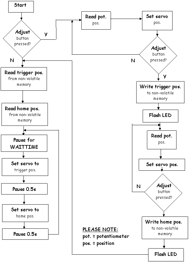
When starting to think about the software code, a flow diagram may help explain what waht you want to achieve. Remember there are often many different software solutions:
Experiments with coding and components are carried out on a temporary 'bread board' before a final design for the program and electronic circuit are decided. Soldering sockets and hardware is one of the last operations in prototype development.
Coding
Launch the PICAXE Programmer and create your own test program to check the functions of the LED and servo on the camera controller or copy the 'timeLapseTest.bas' program below.
'Notes to users are started with an apostrophe “ ' ” sign, which is ignored by the programme compiler and are not part of the code sent to the PICAXE IC.
'Eric Lenard Doel, 30/10/09
'This is a test program (TimeLapseTest.bas) to ensure that all parts of the time-lapse trigger circuit are functional.
'Notes to users are started with an apostrophe “ ' ” sign, which is ignored by the programme compiler and are not part of the code
'sent to the PICAXE IC.
'The program first waits for the pushbutton switch (SW2) to be activated, then flashes the L.E.D. for one second. It then turns on
'the servo and makes it rotate from 0 to 180 degrees and back again over 3 seconds. After that, it links the potentiometer (pot.) to
'the servo in software so that as the user twists the pot. The servo follows it.
| WaitForTrigger: | |
| if pin3 = 0 then WaitForTrigger | 'Wait for the signal from pushbutton switch (SW2) |
| high 0 pause 1000 low 0 |
'Flash L.E.D. for one second |
| for B0 = 0 to 75 | 'Initiate a loop to make the servo rotate in one direction |
| high 1 | 'Ensure servo power transistor is on |
| low 2 | 'Ensure the servo control line is low |
| B1 = B0 * 2 + 75 | 'Calculate a servo pulse length (between 75 and 225) |
| pulsout 2, B1 | 'Send a pulse indicating where the servo should rotate to |
| pause 20 | 'Pause until the next servo pulse |
| next B0 | |
| for B0 = 0 to 75 | 'Initiate a loop to make the servo rotate in the opposite 'direction to the last loop |
| high 1 | 'Ensure servo power transistor is on |
| low 2 | 'Ensure the servo control line is low |
| W1 = B0 * 2 | 'Calculate a servo pulse length 'between 75 and 225). |
| W1 = 225 - W1 |
'W1 is used because an 8 bit variable may have a chance of |
| pulsout 2, W1 | 'Send a pulse indicating where the servo should rotate to |
| pause 20 | 'Pause until the next servo pulse |
| next B0 | |
| ServoControlled: | 'Make the servo replicate the pot. position |
| high 1 | 'Ensure servo power transistor is on |
| low 2 | 'Ensure servo control line is low |
| readadc 4, B2 | 'Read pot. position into B2 |
| W0 = B2 * 150 / 256 + 75 | 'Manipulate B2 into a servo pulse time ( * 10 us) |
| pulsout 2, W0 | 'Send the servo a pulse |
| pause 20 | 'Pause until next servo pulse |
| goto ServoControlled | 'Repeat until power is removed |
'END OF TEST PROGRAMME (timeLapseTest.bas)
Once the LED and servo are seen to be working, try writing software code or load the program “timeLapseMain.bas”, as listed below.
'BEGINNING OF TIME LAPSE PROGRAM (timeLapseMain.bas)
'20/09/09 Eric Doel
'Notes to users are started with an apostrophe “ ' ” sign,
'which is ignored by the programme compiler and are not part of the code sent to the PICAXE IC. '
'START UP
'If pin 3 is pulled high (i.e. if the black button is depressed (SW2)) when the PICAXE is turned on,
'it flashes the LED connected to pin 0 for one second.
'The PICAXE reads the voltage output from the potentiometer (pot.) connected to pin 4,
'and uses this data to position the servo connected to pin 2.
'Because the servo has a range (in data) lower than that of the pot. (75–225 as opposed to 0–255), the pot.
'reading is manipulated so that the full pot. range corresponds to the full servo range.
'Pin 1 is set high during this process to supply power to the servo.
'The user first positions the servo (within a second of startup), by rotating the pot.
'so that the servo arm is pressing down on the shutter button (i.e. taking a photo).
'When pin 3 is pulled high, (the black button is pushed (SW2)), the LED connected to pin 0 is flashed,
'the servo position is stored in non-volatile memory position 0 and the PICAXE pauses for half a second.
'The user then adjusts the servo so that it is off the shutter button and not interfering with the controls,
'then pulls pin 3 high again (by pushing the black button (SW2) again).
'The PICAXE stores this position in non-volatile memory position 1, then flashes the LED
'again for a half second.
'If pin 3 was not pulled high (the black button (SW2) is not pushed) when the PICAXE was turned on,
'as long as the user has not changed the position of the servo or connected the circuit to another camera;
'the servo home and trigger positions are the same; and therefore the program starts from here.
'This means there is no need to make time consuming adjustments.
'The servo home and trigger positions are loaded from memory positions 0 and 1 respectively, into the PICAXE RAM.
'The servo is powered and set to activate the shutter then move to the home position.
'Power is removed from the servo for a predetermined period of time.
'This is repeated until the main power supply is removed.
'For debugging purposes, an extra piece of code has been added to record the number of times that the camera is
'triggered during the power-on session is stored into non-volatile memory address number 2.
'To read the number of triggers that occurred during the last power-on period, start the PICAXE programming editor,
'press F6 (or PICAXE >> Debug) to bring up the debugging screen, then connect the programming cable to the circuit
'and finally apply power to the circuit. The number of triggers that occurred during the last power-on period
'will be shown in register B0 and may be compared with the number of image files from the camera.
'THE TIME LAPSE PROGRAM (timeLapseMain.bas) STARTS HERE
| symbol WAITTIME = 1 | 'The user can change this period between photos, 'measured in minutes |
| read 2, B0 | 'Read the last trigger count into B0 |
| debug B0 | Send trigger count to computer |
| B0 = 0 write 2, B0 B6 = 0 |
'Reset the trigger count |
| if pin3 = 0 then ReadPos | 'If unit is started without the adjust button pressed (SW2) skip 'adjust sequence and load servo positions into RAM |
| high 0 pause 1000 low 0 |
'Otherwise flash L.E.D. for one second and obtain new servo 'positions |
| ShutterAdjust: | 'User sets shutter triggering position |
| high 1 | 'Ensure servo is on |
| low 2 | 'Ensure servo control line is low |
| readadc 4, B2 | 'Read pot position into B2 |
| W0 = B2 * 150 / 256 + 75 | 'Manipulate B2 into a servo pulse time ( * 10 us) |
| pulsout 2, W0 | 'Send the servo a pulse |
| W0 = 2000 - W0 / 100 | 'Calculate the time remaining until the next servo pulse '(Should return 18, 19 or 20 ms) |
| pause W0 | 'Pause until the next servo pulse |
| if pin3 = 0 then ShutterAdjust | 'Repeat until pin 3 is pulled high |
| high 0 | 'Pulse LED |
| pause 500 | ‘Wait ½ a second |
| low 0 | |
| write 0, B2 | 'Write trigger position into location 0 |
| HomeAdjust: | 'User sets "Home" position, i.e. the position the servo will rest at |
| high 1 | 'Ensure servo is on |
| low 2 | 'Ensure servo control line is low |
| readadc 4, B3 | 'Read pot position into B3 |
| W0 = B3 * 150 / 256 + 75 | 'Manipulate B3 into a servo pulse time ( * 10 us) |
| pulsout 2, W0 | 'Send the servo a pulse |
| W0 = 2000 - W0 / 100 | 'Calculate the time remaining until the next servo pulse '(Should return 18, 19 or 20 ms) |
| pause W0 | 'Pause until the next servo pulse |
| if pin3 = 0 then HomeAdjust | 'Repeat until pin 3 is pulled high |
| high 0 pause 500 low 0 |
'Pulse LED |
| write 1, B3 | 'Write home position into location 1 |
| ReadPos: | 'Read trigger and home positions into RAM |
| pause 1000 | 'Give Cap. a chance to stabilise |
| read 0, B2 | 'Trigger |
| read 1, B3 | 'Home |
| Main: | |
| for B4 = 1 to WAITTIME | 'Wait for a predetermined period of time |
| for B5 = 1 to 60 | 'Turn servo off |
| low 1 | |
| pause 1000 | ‘Wait one second |
| next B5 | |
| next B4 | |
| high 1 | 'Turn servo on |
| B6 = B6 + 1 | 'Increment trigger counter |
| write 2, B6 | 'Write trigger counter into non-volatile memory location number 2 |
| gosub Trigger | 'Trigger camera |
| goto Main | |
| Trigger: | |
| for B4 = 1 to 25 | 'make servo travel to shutter for 0.5s |
| high 1 | 'Ensure servo is on |
| low 2 | 'Ensure servo control line is low |
| W0 = B2 * 150 / 256 + 75 | 'Manipulate B2 into a servo pulse time ( * 10 us) |
| pulsout 2, W0 | 'Send the servo a pulse |
| W0 = 2000 - W0 / 100 | 'Calculate the time remaining until the next servo pulse '(Should return 18, 19 or 20 ms) |
| pause W0 | 'Pause until the next servo pulse |
| next B4 | |
| for B4 = 1 to 25 | 'make servo travel back to home position |
| high 1 | 'Ensure servo is on |
| low 2 | 'Ensure servo control line is low |
| W0 = B3 * 150 / 256 + 75 | 'Manipulate B3 into a servo pulse time ( * 10 us) |
| pulsout 2, W0 | 'Send the servo a pulse |
| W0 = 2000 - W0 / 100 | 'Calculate the time remaining until the next servo pulse '(Should return 18, 19 or 20 ms) |
| pause W0 | 'Pause until the next servo pulse |
| next B4 | |
| low 1 | 'Turn servo off |
| return | 'Go back to the main function |
'THE TIME LAPSE PROGRAM ENDS HERE
Parts List
| Semiconductors |
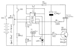
Schematic diagram of the time lapse camera controller |
|||||||||||||||||||||
| 1 PICAXE 08M (IC 1) | ||||||||||||||||||||||
| 1 Darlington BJT (BD 681;NPN) (Q1) or BC 337 (cheaper) | ||||||||||||||||||||||
| 1 green LED (LED 1) | ||||||||||||||||||||||
| Capacitors | ||||||||||||||||||||||
| 1 1 μF polyester (C1) | ||||||||||||||||||||||
| 1 4 700μF electrolytic (C2) | ||||||||||||||||||||||
| Resistors (0.25W) | ||||||||||||||||||||||
|
||||||||||||||||||||||
| Sockets | Other hardware | |||||||||||||||||||||
| 1 8 pin IC socket | 1 4 x AA battery box/holder | |||||||||||||||||||||
| 1 3 pin header socket (male) | 1 6V servomotor (from radio controlled model) | |||||||||||||||||||||
| 1 3 pin header socket (female) | 1 piece of printed circuit (PC) strip-board 30mm x 60mm (free from Bright Sparks) | |||||||||||||||||||||
| Insulated hook-up wire for flying leads and jumpers | ||||||||||||||||||||||
| Switches | 4 AA NiMH cells and charger | |||||||||||||||||||||
| 1 SPST switch (SW1) | Soldering iron, solder and hand tools including digital multimeter, ruler, callipers, files, drill and bits, centre punch | |||||||||||||||||||||
| 1 momentary on switch (SW2) black | Enclosure, machine screws and nuts for securing the servo | |||||||||||||||||||||
 The circuit board
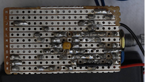
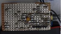
The track side of the PCboard showing tracks cut with a 3 mm drill. For convenience on the prototype, a small component and jumper have been soldered on the track side of the board. In the final version, these parts should be connected on the top of the board.
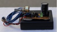
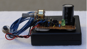
All components are populating the board and it sits on a battery box cover using Blu-tack to hold it on the lid. The Blu-tack not only holds the circuit board, but provides clearance for the components on the track side. The battery box contains 4 x 2.4 Ahr AA 1.2 Volt rechargeable NiMH cells.
Check to see you have all the components on the list or suitable substitutes. Where possible, verify with a multimeter to see that all the components work and that their values are correct. On the track side of the printed circuit (PC) board, cut tracks to isolate the 8-pin IC socket legs. Next solder components such as resistors, jumpers, sockets and headers. Be sure polarised parts are correctly placed.
Be sure all components are sitting against the PCboard and at all stages check to see connections are sound and solder bridges are removed. Finally add flying leads for the switch and power supply then install the polarised components such as the LED, capacitor and transistor, followed by the potentiometer and sockets.
Power up the board and check that voltage values are correct for the location before installing the 8- leg PICAXE 08M integrated circuit (IC).
 Adapter plate
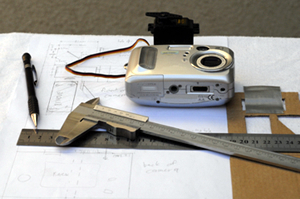
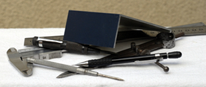
First measure and make a full-scale drawing of the camera and the servo. Next, cut a cardboard template using the measurements from the full-scale drawing. If adjustments need to be made, it is easier to make another template than recut, modify or restart the adapter plate with a new piece of metal. The camera and servo are assembled in the template to see that alignments and clearances are OK. The servo arm should contact the centre of the shutter button. At this stage check to see that camera function is not made more difficult by the adapter plate. It would be easier to use the camera without having to remove it from the plate for battery changes, memory card installation, menu operations and so on. However, the prototype does need to be removed from the plate for battery changes but with more thought this issue may be able to be designed out of the system. Do not forget the camera mounting hole, a brass or stainless steel ¼” NC wingnut and bolt.
It was decided to build the adapter plate from aluminium, so a 200-mm length of 100 mm x 50 mm x 2 mm box section was bought from an aluminium door and window manufacturer. The box-section aluminium was cut to produce a piece of right-angled material and the final design was drawn onto the metal with a sharp pencil or fine felt-tipped pen to reduce scratching the powder coating. Once all of the hole-centres had been marked, they were centre punched and drilled with the smallest drill to be used. The small hole becomes a pilot hole for the larger drill sizes.
Once all the holes have been drilled to their correct sizes, a hacksaw or jigsaw may be used to cut out excess material before all the cuts are smoothed with a file so that the end-user does not get cut by sharp pieces of metal. The builder should run a finger round all of the cuts as a final check to see that no sharp edges remain.
Insert and attach the servo and camera carefully to the adapter plate ensuring neither are scratched or damaged.
 |
 |
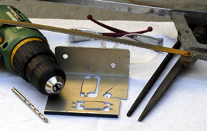 |
| L to R: pencil, ruler, callipers, digital camera, servomotor and cardboard template all sitting on top of a working drawing of the adaptor plate. | L to R: callipers, ruler, scriber, centre punch, dividers and pencil with the powder-coated aluminium resting on top of the tools. | L to R: battery drill, drill, adapter plate, safety glasses, round file and flat file with a hacksaw over the top. |
Set-up and action
Before installing the camera, check the servo works to its full range via the pot and that the trigger and home positions behave as expected. The trigger and home positions can be reset with the ShutterAdjust and HomeAdjust coding or recheck the program coding. Due to the 4700-μF electrolytic (C2) capacitor, when re-setting the trigger position, be sure the PICAXE voltage is zero before attempting this operation.
When choosing a subject, spend some time studying it so the camera can be placed to the subject’s advantage. If sun shadows are used, find out the length and directions of the shadows so the camera can be sited where the shadows will not be 'cut off'. It may be useful to set up a 100-mm vertical pole in the camera view.
If working outdoors, be sure to protect equipment from the elements by setting up a temporary shelter or install the gear in a rainproof enclosure.
See a separate sheet of suggestions for compiling photo files into a video using Windows Movie Maker (MM), a free download for the Windows XP operating system. More »
MM plays still photos at about 8 frames per second with minimum times for Picture duration and Transition duration (see hint above). To calculate the length of time a video will run, decide on the interval between photos, multiply by the length of time the subject will be photographed, then divide by 8.
To use this project as an entry into a Bright Sparks Competition, it is recommended that the circuit is mounted in an enclosure complete with logo, control and LED labels. A log/diary of events/decisions/mentor help is also helpful documentation for judges to reference. Bright Sparks will send free circuit boards to students registered on their website
Using the prototype controller and 4 x 2.4 Ahr AA NiMH cells, the servo gave about 700 shutter actuations. When the power supply voltage dropped, the servo arm did not return to the home position and finally did not have the energy to trigger the camera shutter although the motor continued to run.
With some experimentation, this project could be adapted for use in photographing wildlife. The camera could be triggered by many other sensors such as pressure pads, mercury switches, light beams, micro switches and motion detectors.
Using infrared (IR) light instead of visible light may make this project suitable for use in low-light situations such as in bush or at night. It is possible to buy or construct IR beams and it is also possible to modify an old digital camera to increase its IR sensitivity.
Try optimising the controller project. Using energy conservation software coding will allow the controller to be left for greater periods of time without battery replacement. Later versions of the PICAXE programme and IC have commands that allow reduced current draw when the hardware is on standby. You could also reconfigure the PC board to allow the electronics to be fitted into a smaller enclosure or you could design and etch your own PC board.
By Eric Doel with photographic assistance from Len Doel, November 2009.
Acknowledgements
Many thanks to Andrew Hornblow (Bright Sparks Facilitator) and Alina Arkins for advice and corrections made during the writing of this project.